Tools
Troubleshooting
Keywords
Acknowledgment
Disclaimer
Pages (Latest 3 updated) :
River Builder
Introduction to River Builder
River Builder is an R package, which is available on CRAN. This R package emulates near-census natural rivers as a function of site-specific, reach-averaged, geometric parameters. Pasternack et al. (2018a, 2018b) introduce the ecomorphological and river classification principles implemented in River Builder. The geometric parameters constitute synthetic river valleys, which represent nature-like alluvial channel beds and floodplains. The conceptual approach for designing synthetic river valleys with River Builder is described by Brown and Pasternack (2019) and Brown et al. (2014).
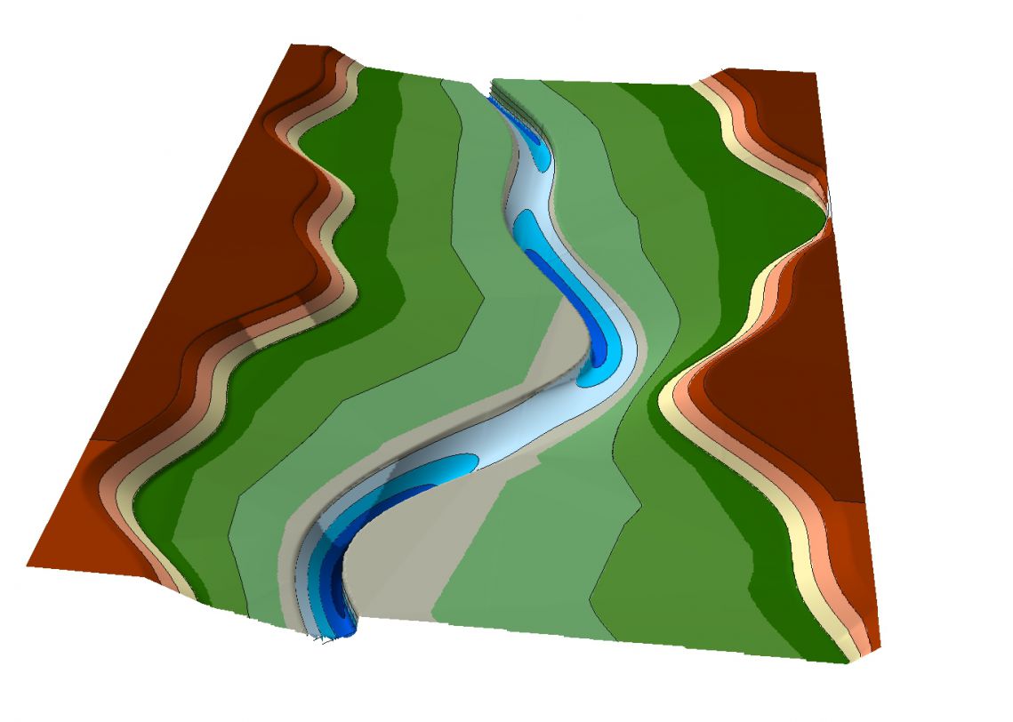
Synthetic river valley created with River Builder (credits: Gregory B. Pasternack).
The synthetic river valley concept produces geodata that can be imported in GIS software (see above illustration) but without reference to real-world coordinates and hydraulic boundary conditions.
The boundary conditions for River Builder are defined by a user-defined input file and River Architect enables the creation of such input files with graphical support. As a result, River Builder can be run within River Architect (therefore rpy2 is required).
We are working on automating the creation of input files in River Architect to the extent that synthetic valleys can be translated into real-world coordinates and reflect hydraulic conditions of real rivers.
Please note that River Builder has an own detailed user manual. This wiki primarily describes the usage of River Builder within River Architect.
To use the River Builder interface within River Architect, click on the Morphology tab and go to the ModifyTerrain sub-tab (default). Selecting the none Condition (confirm with a click on Select Condition) enables (unfreezes) the RIVER BUILDER frame.

Create Input Files
Click on the Create RB Input.txt File button to create a new input file for River Builder. The following window will pop up.

Make sure to define an input file name (top of the popup window) without entering a file ending. Define all required parameters (i.e., all parameters without any asterisk* in the left column of the popup window). A click on the Info buttons opens the parameter descriptions (adapted from River Builder’s user manual).
The following list summarizes the required parameters and their default values (original descriptions from River Builder’s user manual):
- DOMAIN PARAMETERS (IN METERS)
- Datum: FLOAT [1.0=default] - a fixed starting point of operation to measure changes of a specific property. Used for thalweg elevation. This datum is located at the downstream end of the synthetic river valley, and then the river goes up from there. Thus, if the datum is set as any number > 0, then it is guaranteed that all elevations in the valley will also be > 0. You may set any arbitrary number you wish. If you want to estimate the total elevation range of the thalweg along the river, then simply multiply your Valley Slope input by the Length input and that will give you the overall elevation range of the thalweg. For example, for a 1000 m long channel and a Valley slope of 0.01, then thalweg elevation range is going to span 10 m.
- Length: FLOAT [100.0=default] - the length of the x-axis of the river valley. This is only the channel length if the river is straight. If the river is sinuous, then this length is the valley length and the actual channel length will depend on the sinuosity. Sinuosity is computed by the model and reported in the Data.csv file, so you can compute the final channel length if you want to know it.
- X Resolution: FLOAT > 0.0 (e.g., 1.0 [default] = 1-m resolution) - the resolution of equally spaced data points spaced along the X-axis in units of meters. There is no limit to how fine the point spacing can be, other than computation time for your computer. The smaller this number, the longer the code will take to run. Use your judgment to decide how much detail you need given the scale of your river and the resolution of the sub-reach variability functions you are applying. There is no need for extra detail if the river is easily interpolated with fewer data.
- Channel XS Points: INTEGER > 1 [23=default] - the number of equally spaced points defining the channel’s cross-section. This is not applied outside the channel, only in it. Beyond the channel, River Builder provides you with points along the major breaklines, and then you can interpolate the terrain between those on your own later using a TIN approach. For field data collection in a U-shaped channel, people commonly use approx. 15-30 points. An odd number is wise if you want to have a line of output points exactly in the center of the channel.
- DIMENSIONLESS PARAMETERS (-)
- Valley Slope Sv: FLOAT [0.001=default] - the slope of the valley floor along the X-Z plane. It is used to calculate the overall channel slope with a given sinuosity and govern the incline/decline of the surrounding valley.
- Critical Dimensionless Bed Shear (aka “Shields) Stress* τ*, cr, D50: FLOAT [0.047=default] - If you are going to specify a bankfull depth, then set this value to zero. If you want to use the classic equation to establish a bankfull depth to just yield the shear stress needed to mobilize the bed for a specified bed material grain size, then you can use this. Common values used for this parameter are 0.03, 0.045, 0.047, or 0.06, depending on what size fraction you want to insure would be mobilized at bankfull flow. The equation that uses this input is Eq. (4) in Brown et al. (2014). Read more on the dimensionless critical bed shear stress for example in Lamb et al. 2008.
- CHANNEL PARAMETERS (METERS)
- Bankfull Width Wbf: FLOAT > 0.0 [10.0=default] - the distance between bank tops on the X-Y plane, not counting any sub-reach variability functions.
- Bankfull Width Minimum: FLOAT >= 0.0 [5.0=default] - the minimum distance between the bank tops on the X-Y plane. This variable is specified to protect the user from making a mistake with sub-reach variability functions in which the banks would cross over, yielding an impossible outcome. This ensures that the river never has a zero or negative width. If you are confident in what you are doing, then you can set this to zero.
- Bankfull Depth Hbf, A: FLOAT [1.0=default] - the height between the thalweg elevation and then bank top and thalweg on the X-Z plane, not counting any sub-reach variability functions. Depending on channel slope and variability functions, the local bankfull depth can differ from this value.
- Median Sediment Size D50: FLOAT >= 0.0 [0.01=default] - the particle size of the material comprising the river bed. This is only used if one has left Hbf = 0 and wants to compute the bankfull depth value associated with the initialization of bed material transport for this specified grain size. This value is used in conjunction with the critical Shields stress value as explained earlier.
- FLOODPLAIN PARAMETERS (METERS)*:
- Floodplain Width*: FLOAT >= 0.0 [default] - double the horizontal distance from the bank top on one side of the river to the outer edge of the floodplain on the same side of the river. Note that if the floodplain has a lateral slope, then this value is still just the horizontal distance, not the slope distance on the floodplain surface. This value is the sum of horizontal floodplain distances for both sizes of the river, so keep that in mind when designing your floodplain. If this number is zero, then there is no floodplain, which yields a confined valley/canyon scenario. If it is a big number, then there is a very wide floodplain. This applies symmetrically to both sides of the river. If you want asymmetric floodplains, then that is handled with independent Left/Right Floodplain sub-reach variability functions.
- Outer Floodplain Edge Height*: FLOAT >= 0.0 [default] - the incremental increase in elevation from the bank top to the outer edge of the floodplain on the Y-Z plane. If this number is close to zero, then the floodplain is essentially flat. If it is high, then the floodplain is sloped.
- Terrace Width*: FLOAT >= 0.0 [default] - double the horizontal distance from the outer edge of the floodplain on one side of the river to the outer edge of the terrace on the same side of the river, making it terrace width. This value is the sum of horizontal terrace distances for both sizes of the river, so keep that in mind when designing your terraces. This applies symmetrically to both sides of the river.
- Outer Terrace Edge Height*: FLOAT >= 0.0 [default] - the incremental increase in elevation from the outer edge of the floodplain to the outer edge of the terrace on the Y-Z plane. If this number is close to zero, then the terrace is essentially flat. If it is high, then the terrace is sloped.
- Boundary Width*: FLOAT >= 0.0 [default] - double the horizontal distance from the outer edge of the terrace on one side of the river to an arbitrary point out on the valley floor on the same side of the river. This allows for a flat, wide domain that could be another terrace or just the open landscape beyond the alluvial river valley.
- USER-DEFINED FUNCTIONS*
- User Functions*: OWN WINDOW (multiple assignments possible [no default]) - Three types of functions (Sine, Cosine, and SineSQ) provide periodic oscillations. As simple as those are individually, remember that you can add as many of them as you want into one overall function, using addition, subtraction, etc. As shown in Brown et al. (2014), it is possible to get some very interesting and meaningful variability patterns with 2-4 SIN() functions added together, using different values for frequency, amplitude, and phase. One way to ascertain what those parameter value could be would be to perform harmonic analysis on real series of river variables, such as bed elevation, width, meander centerline, etc. You can extract all the periodic functions you want from that kind of analysis and use those in your design to whatever degree you wish. Because rivers often do exhibit linear trends in variables, such as width and depth, we have added the linear function for users to create that effect. Sometimes you want to have a function that is deterministic and oscillating, but non-periodic. The best application for this type of function would be for the meander centerline because channel alignment is not going to be truly periodic. To achieve this, we provide a Perlin noise function. To find out what sinuosity you get from a particular set of Perlin parameters, you have to run River Builder and look at the Data.csv file. That is a bit clunky, but it works.
- SUB-REACH VARIABILITY PARAMETERS (REQUIRES USER-DEFINED FUNCTIONS)*
- Centerline Curvature Function*: USER FUNCTION [no default] (multiple assignments possible) - Normally the sub-reach variability functions for centerline curvature would be set equal to those governing the meandering centerline. However, one application of the curvature value is with controlling the asymmetry of a channel’s cross-sectional shape. To provide greater flexibility with how a river’s XS shape changes along the river, we have created a decoupled centerline curvature variable. This variable does not affect the channels meandering. It only affects how channel asymmetry varies down the river. For example, let’s say that you did not want the deepest part of the cross-section to be at the outer bend of a meander, then you could use this to put the deepest part anywhere you want governed by the available variability functions. This is a highly complex tool to control compared to others, so only use it if you know what you are doing with your river design concept.
- Left Floodplain Function*: USER FUNCTION [no default] (multiple assignments possible) - whereas the channel is treated as one entity having a width, the floodplains have been segregated into independent units. This function governs variability in the location of the outer edge of the river left (i.e., left looking downstream) floodplain.
- Right Floodplain Function*: USER FUNCTION [no default] (multiple assignments possible) - governs variability in the location of the outer edge of the river left (i.e., left looking downstream) floodplain.
- Meandering Centerline Function*: USER FUNCTION [no default] (multiple assignments possible) - governs the shape of the river’s tortuous flow path (i.e., meandering or sinuosity) on the X-Y plane. At this time, it is not possible to make gooseneck loops, but the available functions offer a good range of flexibility to mimic diverse sinuosity values. If you do not care about the details of the pattern, but only want to match a sinuosity value, then it is recommended that you use the Perlin function and iteratively adjust the parameters until the sinuosity value in the Data.csv output file matches your target value.
- Thalweg Elevation Function*: USER FUNCTION [no default] (multiple assignments possible) - governs undulations in the bed elevation along the Thalweg on the X-Z plane. Used to create riffle-pool couplets.
- Bankfull Width Function*: USER FUNCTION [no default] (multiple assignments possible) - governs the downstream variability in the distance between bank tops on the X-Y plane. If you create an undulating function, be very careful that the banks do not cross over to create negative channel widths. We have implemented a minimum bankfull width variable to help avoid this, but it is wise to reason out the amplitude of your width function and not have to rely on that safety net. For longer river segments, try a linear function that increases the width in the downstream direction, consistent with geomorphic theory. You can find parameters for the downstream width increase in the geomorphic literature quite easily.
- CROSS SECTIONAL SHAPE
- Cross-Sectional Shape: STRING (“AU” [default], “SU” or “TZ”) - The shape of the cross-section on the Y-Z plane. Input must be AU, SU, or TZ(n), where n is the number of edges that defines the length of the trapezoidal base such that 0 < n < (Y-Z Increments). It is recommended that unless you really know what you are doing with AU or are starting from a good AU template file, then only use SU or TZ. If AU is selected, specify a Centerline Curvature. If TZ is selected, specify n: - Triangle: n = 0 - Trapezoid: 1 <= n <= (Y-Z Increments-2) - Rectangle: (Y-Z Increments-3) <= n <= (Y-Z Increments)
*All parameters with an asterisk are optional.
Please note: Each undefined parameter is assigned a default value and all parameters are METRIC. River Architect uses an internal conversion factor when U.S. customary units are selected in the main GUI’s Units dropdown menu.
A click on CREATE INPUT FILE writes the input file to RiverArchitect/ModifyTerrain/RiverBuilder/INPUT_FILE_NAME.txt.
Select Input Files
Once an input file is created, it can be selected by clicking on the Select RB Input.txt File button. Also, input files can be used when they were not created with the above described GUI, but it is important that these input files are located in RiverArchitect/ModifyTerrain/RiverBuilder/INPUT_FILE_NAME.txt. This restriction is necessary because River Builder can only read input files that are located in the same directory as the River Builder R script (riverbuilder.r).
Run River Builder within River Architect
River Architect uses the rpy2 package to load River Builder (also refer to the River Architect installation instructions).
With an input file selected, a click on the Run River Builder button launches River Builder. Running River Builder may take a couple of minutes. Pay attention to messages on the console, which may indicate if River Builder had issues with the provided inputs.
Output
River Builder writes output files to RiverArchitect/ModifyTerrain/Output/RiverBuilder/INPUT_FILE_NAME/ (note that the output is stored in the Output folder, which is one level above the RiverBuilder folder). The following output files are produced (original descriptions from River Builder’s user manual):
-
BoundaryPoints.csv Contains keys that map to specific points in CartesianCoordinates.csv that comprise the boundary around a river’s floodplain. This is an essential input file for ArcGIS.
-
CartesianCoordinates.csv Contains comma-separated XYZ coordinates for the synthetic river valley. This is an essential input file for ArcGIS.
-
Data.csv Contains coefficients of variation, averages, standard deviations, channel slope, and other important information.
-
ChannelElevation.png Displays the elevation of the river’s channel meander.
- CrossSection.png Displays the river’s cross-section at its midway point. The cross-section is bounded above by the river’s bank top and below by the thalweg.
-
GCS.png Displays the geometric covariance structures of bankfull width and thalweg elevation; thalweg elevation and the channel meander.
-
LongitudinalProfile.png Displays the side view of the river which consists of valley top, valley floor, bank top, and thalweg elevation.
- Planform.png Displays the bird’s eye view of the river which consists of the channel meander, channel bank, valley floor, and valley top.
For rendering the output into 3D graphs, follow the following instructions from the River Builder’s user manual (the steps refer to the usage of ArcMap and a Python script that is provided along with River Builder and included in the River Architect standard installation RiverArchitect/ModifyTerrain/RiverBuilder/RiverBuilderRenderer.py):
- Open ArcMap. Look for the
Catalogtab on the far right of the interface. If it does not show, go toWindows->Catalogfrom the top menu to have it opened. - In
Catalog, locate the directory in which the River Builder toolbox is stored. If the directory is not visible, select Connect to Folder from theCatalogtoolbar, and select the desired directory. - Once the desired directory is visible in
Catalog, expand the toolbox it contains, right-click the River Builder tool, and go to Properties. Under the Source tab, enter the location of where the Python scriptRiverArchitect/ModifyTerrain/RiverBuilder/RiverBuilderRenderer.pyis stored in your local machine. ClickOK. - The River Builder toolbox is now available for use on ArcMap. Select it, and a window will appear. Enter values for the following four inputs:
- Name: The label applied to each output file, i.e.
<Name>_Layer.shp,<Name>_Boundary.shp, etc. - Output Folder: The location in which an output folder named
<Name>will be produced. That folder will contain all the output files generated by the script. - XYZ File: The Cartesian coordinates file produced by the R code.
- Boundary Points: The boundary points file produced by the R code.
- When all the inputs are filled, click
OK, and the script will run. After it is finished running, go to the<Name>folder in the output folder that you specified to access the newly generated shape and raster files.
About
River Builder is maintained by Prof. Gregory B. Pasternack, his co-workers, supporters, and friends. Please visit their website to learn more about the general concepts and updates of River Builder.